Today I’m going to show you exactly how to configure IPSEC failover between a Cisco ASA and A Palo Alto.
Network:
1 ASA, 2 wan circuits
1 Palo, 1 wan circuit
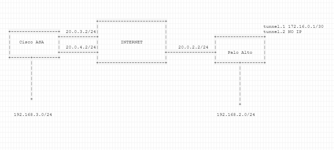
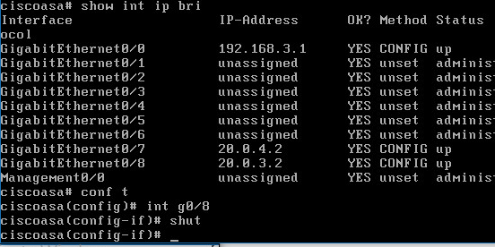
Let’s assume at the ASA side 20.0.3.2 is our primary WAN circuit and 20.0.4.2 is the backup circuit we have just added.
Now let’s configure the Site to Site VPN:
object network LAN

subnet 192.168.3.0 255.255.255.0

exit

object network EASTLAN

subnet 192.168.2.0 255.255.255.0

exit

object network EASTLAN2

subnet 172.16.0.0 255.255.255.252

exit

object-group network EASTNETWORKS

network-object object EASTLAN

network-object object EASTLAN2

exit

access-list VPN extended permit ip 192.168.3.0 255.255.255.0 object-group EASTNETWORKS

nat (inside,outside1) source static EASTNETWORKS EASTNETWORKS destination static EASTNETWORKS EASTNETWORKS no-proxy-arp route-lookup

nat (inside,outside2) source static EASTNETWORKS EASTNETWORKS destination static EASTNETWORKS EASTNETWORKS no-proxy-arp route-lookup

crypto ikev1 enable outside1

crypto ikev1 enable outside2

crypto ikev1 policy 10

authentication pre-share

encryption aes

hash sha

group 2

lifetime 86400

crypto ipsec ikev1 transform-set ESP-AES-SHA esp-aes esp-sha-hmac

crypto map outside_map 10 match address VPN

crypto map outside_map 10 set pfs

crypto map outside_map 10 set peer 20.0.2.2

crypto map outside_map 10 set ikev1 transform-set ESP-AES_SHA

crypto map outside_map interface outside1

crypto map outside_map interface outside2

tunnel-group 20.0.2.2 type ipsec-l2l

tunnel-group 20.0.2.2 ipsec-attributes

ikev1 pre-shared-key PASSWORD

isakmp keepalive threshold 10 retry 5
Now let’s configure the Palo side. This side is going to be mainly screenshots.
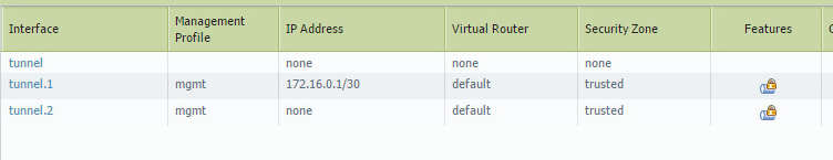
First configure 2 tunnel interfaces, 1 with an IP of 172.16.0.1 and one without an IP. Put them both in the trusted zone so that VPN traffic will flow properly without rules. We require one with an IP because we will be sourcing pings from it later. This network will be advertised to the ASA and this is NOT a route based VPN. This is a policy based VPN. The Cisco ASA does NOT support route based VPN.
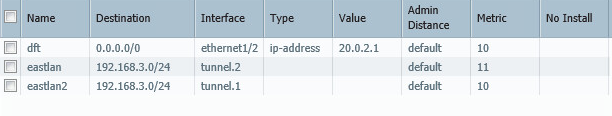
Now create a route for the East lan of 192.168.3.0/24 with the next hop interface as tunnel 1, this tunnel should have a normal distance of 10
Create a second route for the East lan of 192.168.3.0/24 with the next hop interface as tunnel 2, this tunnel should have a distance of 11
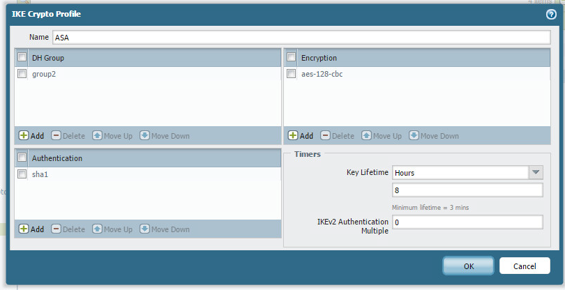
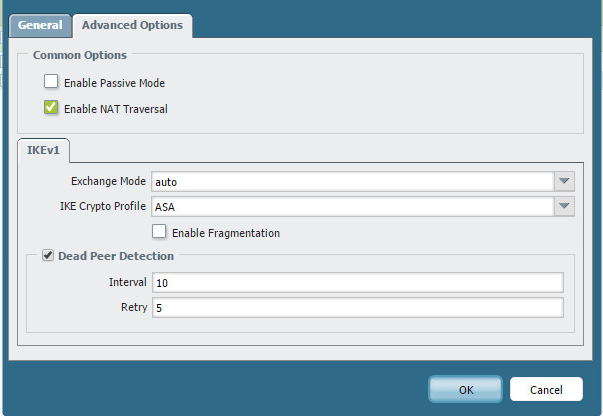
Now create your IKE profile.
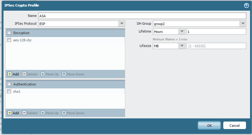
Also create your IPSEC profile.
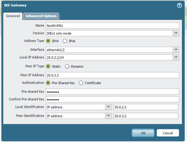
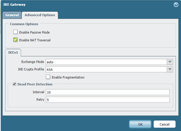
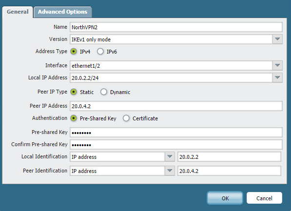
Now we need to create two IKE Gateways, one for each WAN circuit at the ASA.
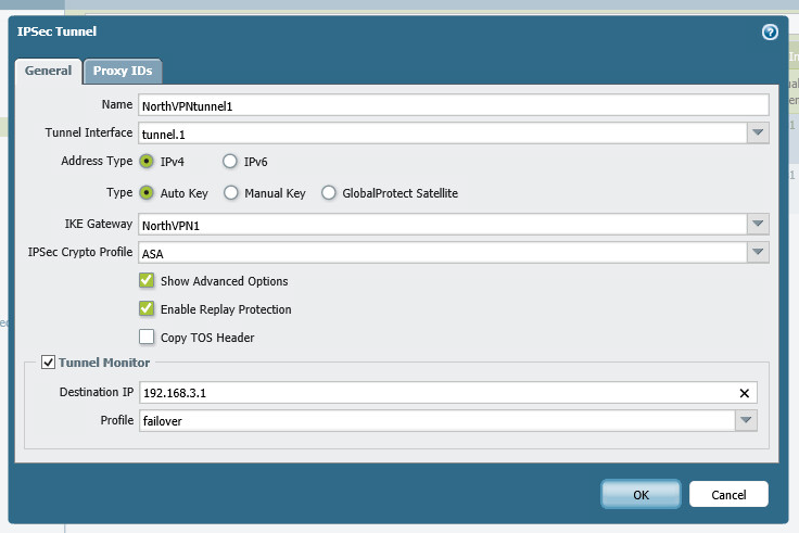
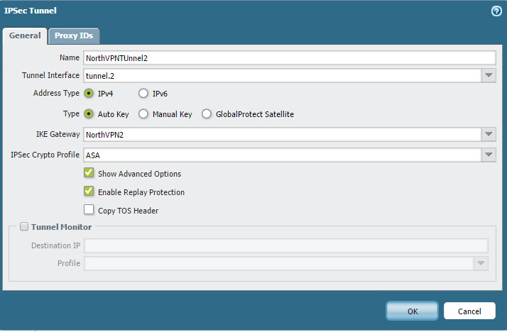
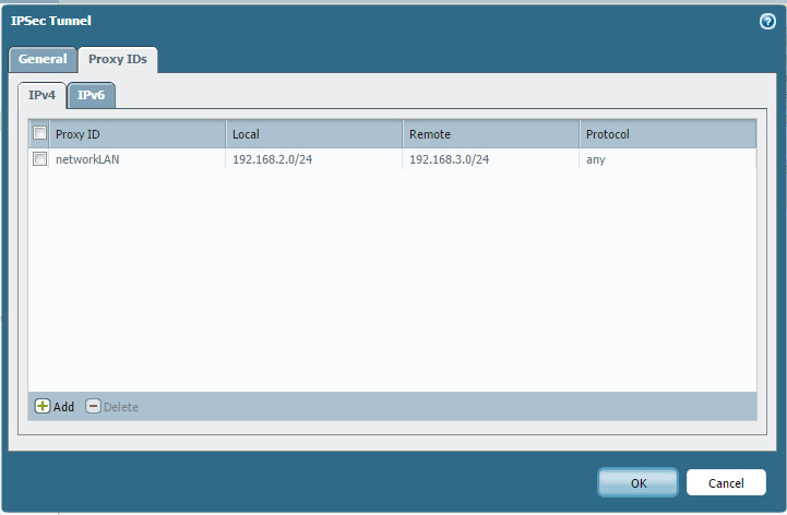
Let’s finish the tunnels off by creating two IPSEC tunnels.
Tunnel one will be to the main circuit of the ASA. Notice on this tunnel we use the “tunnel monitor”. This will send pings to 192.168.3.1 (The ASA’s lan interface). These pings will be sourced from the outgoing interface, tunnel.1 This is why we needed to give it an IP and then advertise that subnet to the ASA. This way the ASA can return pings to 172.16.0.1 and the tunnel will remain up.
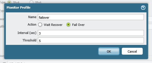
The failover profile I created was this.
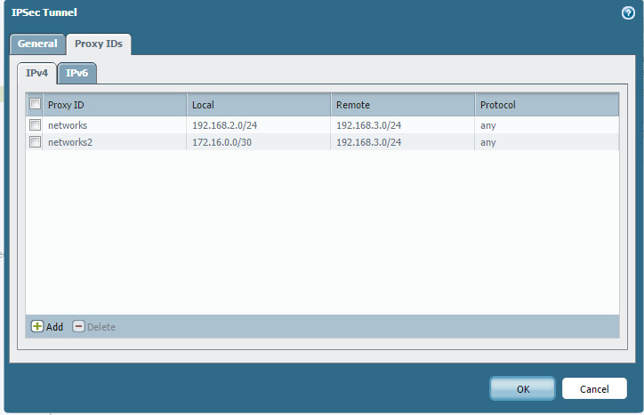
Here’s the second tunnel. Notice here we do not need the tunnel monitor.
That’s it! Now let’s test.
Let’s shut down the main WAN circuit on the ASA.
Boom failover occurred!
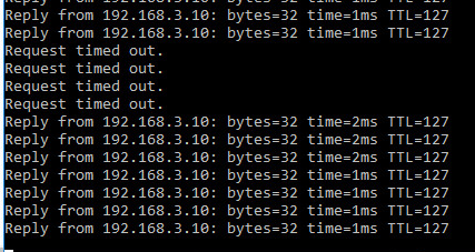
So how does it work? The main tunnel stays up and it’s able to be monitored thanks to the IP on the tunnel.1 interface and the tunnel monitoring. As soon as those poings sourced from tunnel 1 start to fail, that tunnel is torn down and the static route is NOT “active”. This means our backup route takes over and is able to negotiate the tunnel with the second wan interface.