Table of Contents
2.1.g (i) SPAN, RSPAN, ERSPAN
SPAN
What problem does it solve?
Switchport analyzer (SPAN)
We need visibility on the traffic coming into our LAN. We have a network monitor device that we want to send copies of the frames to. SPAN ports allow you to mirror a port to another one so you can capture unicast data on the side.
In span you define the source and destination ports, the source being the original port you want to clone.
You can choose to copy ingress, egress or both.
Local SPAN – the source and destination ports all belong to the same switch
Remote SPAN – The source and destination ports are not on the same switch.
Remote SPAN requires a trunk since RSPAN traffic is on a different vlan.
There’s a third type of span called ERSPAN (enhanced). Encapsulating frames into GRE then IP so it can be routed to a destination. The CCNP doesn’t get into this.
SPAN or RSPAN sources:
You can define one or more ports
One or more vlans
One or more directions tx, rx, or both.
Traffic to from the switch CPU
Remote VLAN.
SPAN dest:
One or more ports ( for local span)
One or more remote vlans (for rspan)
A port identified as a SPAN Destination has other features on it disabled.
The port won’t be able to be used for any type of data or transmit.
The only thing that happens is frames are copied and sent to this port.
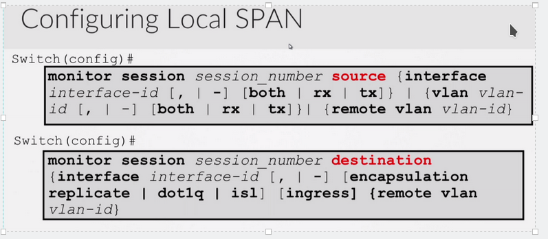
Ex:
Monitor session 1 source int g0/1 both
Monitor session 1 destination int g0/2
We can use : show monitor which will show you your sessions
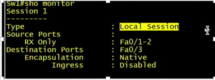
![]()
The show int shows as monitoring.
The LED lights on the switch show the port as up.
To remove the span you can use:
No monitor session 1
Or
No monitor session all
RSPAN
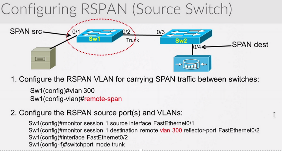
On switch 1 and 2 you would configure vlan 300 as remote span. Then configure the span session, the source of the rspan vlan (300), and the destination of f0/4
Don’t forget to confirm the trunk settings allow vlan 300.
Now finish the config on sw2
Sw2#
Conf t
Vlan 300
Remote-span
Exit
Monitor session 1 source remote vlan 300
Monitor session 1 destination int g0/4
Rspan is very similar in config to span except now you would configure a vlan as your remote-vlan.
You do this by creating a vlan and then specifying remote-span in vlan config. ( on all switches)
You would then configure your trunk on both switches so that the rspan vlan can traverse it.
Then finally in the span config, instead of a physical interface, you choose remote vlan.
Sometimes the reflector-port keyword/parameter isn’t needed depending on your switch.
Your reflector-port is NOT the trunk port. The reflector port is responsible for copying the span traffic onto the rspan vlan. The reflector port should not be the trunk port. It becomes unusable. It is a way of donating asics to the cause of rspan. You should choose a port that is not being used.
VTP does work with the RSPAN vlan, it will propogate it to all switches assuming it was created on the VTP server. If it wasn’t you will have to manually configure it along the path.
VTP prunning will also prune the RSPAN vlan if there are no ports in that vlan.
MAC address learning is disabled for the RSPAN VLAN.
Remember ports in different vlans can be source ports, and so can trunk ports.
A port-channel can also be a source port.
ERSPAN
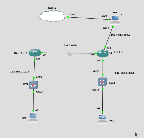
There are two ways to configure this:
1. ERSPAN session between routers
2. Send ERSPAN traffic to a PC
Here is the most common way to do this, and the supported Cisco way. Basically send the GRE encapsulated SPAN session to R2, who then sends it out to G3.
R1:
monitor session 1 type erspan-source
no shut
source interface Gi2
destination
erspan-id 100
mtu 1464
ip address 10.0.0.2
origin ip address 10.0.0.1
Now you will notice that all traffic from interfaceG2 on R1 is encapsulated in GRE, and sent over to 10.0.0.2 (R2).
R2:
monitor session 1 type erspan-destination
no shut
destination interface Gi3
source
erspan-id 100
ip address 10.0.0.2
When the packets are passed to int g3, they go out normally, decapsulated.
However in the middle, between R1 and R2, during the SPAN Session, we can capture the GRE tunnel.
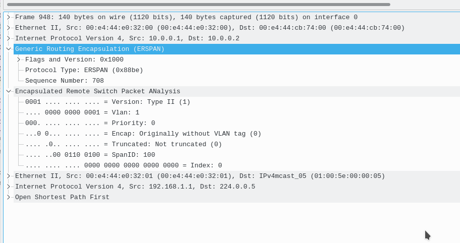
############################################################################
here is an ERSPAN session where R1 sends the packets encapsulated in GRE to the PC of 192.168.3.2 WITHOUT using R2.
R1:
monitor session 1 type erspan-source
no shut
source interface Gi2
destination
erspan-id 100
mtu 1464
ip address 192.168.3.2
origin ip address 10.0.0.1
Now you will notice that all traffic from G2 on R1 is encapsulated in GRE, and sent over to 192.168.3.2
Note that this traffic is NOT decapsulated, and thus you will see the GRE headers within wireshark on the client.