Table of Contents
2.1.f (i) PVST+/RPVST+/MST
802.1D Classic STP and PVST+
Note that when focusing on legacy spanning tree, we are actually focusing on per vlan spanning tree + which runs classic STP per vlan. We don’t actually have the option of 802.1D or classic spanning-tree in our switches.
Before we begin you should know what a burned in mac address is (BAI MAC) it’s the hardware mac address of the switch that you cannot change, it is how we will identify the switch.
So how does it work?
First switches elect a root bridge
Then switches elect one root port
Finally we elect designated/downstream ports
Any ports left over should be in the blocking state.
Root bridge Election:
The lowest bridge ID in the L2 network is the winner.
The bridge ID contains 3 things:
Bridge priority + system ID ( default 32768, range of 0 to 61440, in increments of 4096 (lower is better))
MAC address (the mac address of the switch)
By default the lowest mac address becomes the determining factor.
However if we wanted to actually carve out the L2 path and elect a root bridge properly, we would need to edit the priority. Priority takes precedence in the Bridge ID.
How to manually change the bridge id to elect a root bridge?
en
conf t
spanning-tree vlan <vlan> priority <number>
We can also use:
spanning-tree vlan <vlan> root <primary | secondary >
The command above looks at who is currently their root bridge, and picks a bridge priority lower than that to beat it. If you choose secondary then it will pick the second highest.
verification:
show spanning-tree vlan <vlan>
show spanning-tree root
Now that we know how the “root” bridge is elected, let’s get into some details.
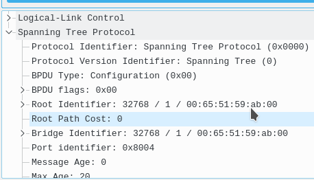
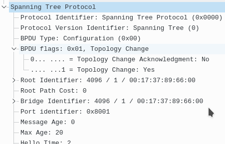
Bridge protocol data units (BPDUs) are sent every 2 seconds by default. In this case when switches come online, they will all elect to be the root, only until they receive superior BPDUs will they stop transmitting their own bridge ID as root but their will transmit the elected root. You should remember that BPDUs really carry two pieces of information, the current bridge ID and the root bridge id.
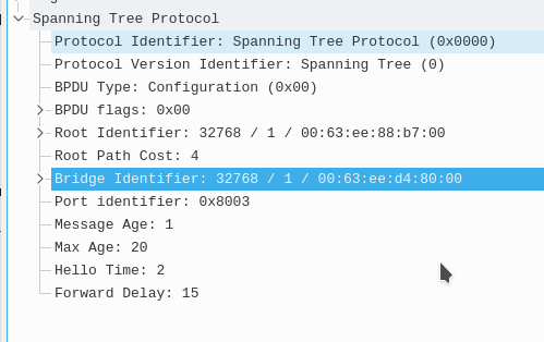

Notice in the above packet capture this BPDU shows this bridge, and then the root bridge. Just by looking at this we can tell that the root bridge was elected so because of the lower MAC address.
Port states:
When ports initially come up in 802.1D they go into different roles, first they go from disabled to listening state (15 sec listens for BPDUs), then the learning state (15 sec learns mac addresses) then finally a switch can choose to go blocking or forwarding. Blocking being not allowing traffic to pass, but still listening for BPDUs. Forwarding being sending, receiving data and BPDUs.
Here are two switches, the blue switch is already connected to the network and has a good root bridge with a BID of 0 + 1 vlan
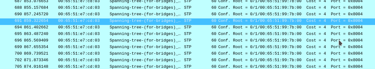


A pink switch comes online and thinks he’s hot stuff, tries to declare himself root. Then he sees the better BID and stops transmitting himself as root on his root port.
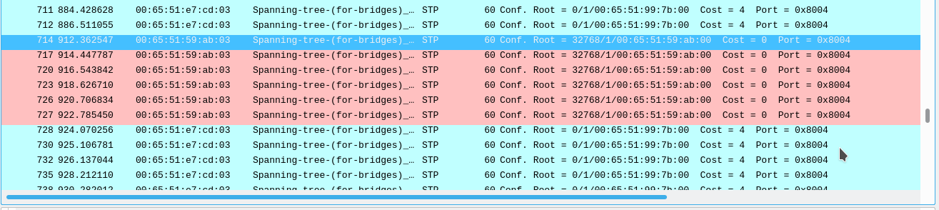


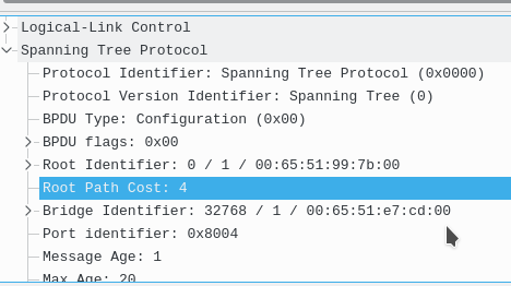
Instead now he just listens on his root port for those BPDUs, and on his designated ports he sends this new root out. Here’s the BPDU he’s now sending on his designated ports.

That completes the lesson of how the root bridge election happens. This continues to happen down stream until everyone has converged.
So again those port states are:
Disabled Not doing anything, shutdown
Listening (listen for BPDUs = to forward delay time) (15 sec)
Learning (Learn mac addresses = to forward delay time) (15 sec)
Blocking (not forwarding but listens for BPDUs)
Forwarding ( forwarding traffic AND listens for BPDUs)
There are also port roles in 802.1D:
Root (leads to root bridge)
Designated (leads to downstream switches or end hosts)
Blocking but shows up as Alternate on Cisco (a redundant inferior path to the root bridge)
Root port election:
1. The port with the best cumulative “cost” to the root bridge becomes the root port. All other paths to the root are blocked.
All non root paths are put into designated forwarding (downstream ports). For a 100Mbps like the cost to root is 19, for 1 Gbps it is 4. If both ports have the same cost to the root bridge they then compare upstream bridge IDs, the bridge ID we receive with the better priority or lower mac if that ties wins. If that is the same we are probably connected to the same switch with two equal links. In this case the next tie-breaker is upstream port priority and port number (128.x). By default the priority is the same (128) for all ports. The upstream BPDU we receive that has the lower port number wins if we did not have a port priority set. (NOT THE LOWER PORT NUMBER LOCAL TO OUR SWITCH)
note about cost: When switches send BPDUs downstream to designated ports they advertise the total cost to the root that they had + the cost of their root port. When you run “show spanning-tree” you are seeing the root cost or the cost that is sent to you. You need to add in your root port’s cost to that calculation for total cost.
A cost of 0 means we are directly connected to the root bridge.
NOTE: In 802.1D Spanning-Tree switches do NOT send BPDUs on Root, or Alternate ports. In fact they only send BPDUs on designated ports. The only exception is a TCN BPDU to the root bridge and during bridges coming online.
To verify or get more info you can use:
show spanning-tree detail
Designated port rule:
There must always be 1 designated port PER segment
Designated port election:
This process is based on same thing:
lowest path cost to root, lowest bid, lowest port id
All other ports go into blocking more
Timers:
Regarding STP timers, by default they are:
hello time 2,
max age time 20 (dead interval)
forward delay time 15 (how long to wait between listening and learning)
Changing these per switch has no meaning. Only the root bridge can set these and propagate them down.
How to change them?
conf t
spanning-tree vlan 1 hello-time 1
spanning-tree vlan 1 forward-time 8
spanning-tee vlan 1 max-age 10
verification:
show spanning-tree
Modifying paths:
There are a couple of different ways to do this.
The first way is to modify the cost:
conf t
int g0/1
spanning-tree vlan <vlan> cost <cost>
bandwidth <bps>
We can modify bridge id
conf t
spanning-tree vlan <vlan> priority
Modify port id (for when the port priority tie breaker comes):
conf t
int g0/1
spanning-tree vlan <vlan> port-priority
verification:
show spanning-tree int <int> detail
show spanning-tree vlan <vlan> detail
TCN Behavior:
When a port NOT configured for portfast goes from learning to forwarding, OR down, the switch will send a TCN BPDU towards the root bridge on it’s root port.
Once that TCN BPDU is sent to the root, the root sends back Topology Change acknowledge (TCA) BPDU back to the switch.
Then the root bridge then sends a config + TCN bpdu to all switches, the root bridge does this for max age + forward delay (20+15=35 sec) by default.
This tells the other switches to set their CAM/MAC aging time from 300 sec to whatever the MAX age time is (default 20 sec)
Here is the section I wrote up for portfast explaining TCN behavior in 802.1D
Here is an example.
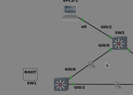

We are on SW2 and we bring up the link of g0/2 to a host, that IS configured for portfast.
This is the only BPDU that came on the link between SW(root) and SW2(non-root).
We get what we expected, only BPDUs from root (SW2 will never send BPDU on it’s root port)
That’s what port-fast does, it prevents TCN BPDUs from being sent out.
Now here is the same example, but let’s run the command to remove portfast “no spanning-tree portfast” on that int g0/2
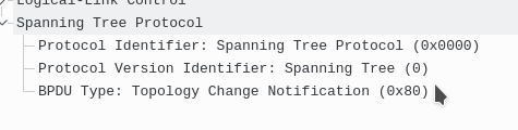
Now here is the capture from the link between SW1 and SW2. SW2 who normally never sends BPDUs out of it’s root port now sends a TCN BPDU via it’s root port.
SW2 also sends a TCN BPDU

Now here is SW1(root) sending the TCA BPDU back to SW2 acknowledging the message.
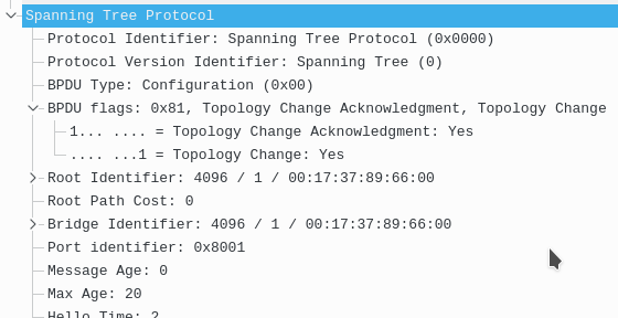

Now SW1(root) sends this BPDU out to ALL switches in the tree stating they need to set their CAM table timeout to max age, in this case 20 sec (default)

Rapid Spanning-Tree
Most of the things we discussed in 802.1D are carried over, even the toolkit features.
Rapid Spanning-tree Protocol is the new algorithm for the calculation of the tree.
The IEEE standard is 802.1W.
What has changed?
3. Simplified port states
in RSTP we just have 3 port states
2. additional port roles
We have alternate, backup and edge ports now
1. Rapid convergence
Utilizing a process called synchronization (a handshake between switches with BPDUs)
What once took 30 seconds to start a link now is instantly.
RSTP port states:
Discarding (dropping frames)
Learning (drop frames building CAM)
Forwarding
The port roles are now NOT tied to the states.
New roles:
Alternate – A port towards the root bridge with a worse cost (uplinkfast now built into 802.1W).
Operates in the discarding state.
Backup – A backup designated port (downstream, rare, means you have multiple links into a HUB or dumb L2 switch) (is a backup for the designated port)
Operates in the discarding state.
Edge – Portfast is now built into RSTP, immediately transitions to forwarding, do not generate tcn, configured with “spanning-tree portfast edge”
These edge ports lose their edge status and go through listening and learning if they detect a BPDU coming in. This is automatic.
TCN behavior change –
In previous versions of STP the TCN behavior was the switch sends a TCN to the root bridge and then the root bridge generates a config BPDU with TCN flag to forward downstream.
Now what happens is a TCN is generated, it’s forwarded out all forwarding ports, then when a switch receives this frame, it will flush it’s cam table (for that vlan) out on all ports except the one the BPDU came in on. The topology must be rebuilt doing unknown flooding.
New Link types:
non edge ports (switch to switch):
point to point – full duplex
Shared – halfduplex link
ONLY point to point, non edge, designated ports use the sync process.
Setting RSTP port- types:
spanning-tree link-type <point-to-point | shared>
Sync process:
The sync process in RSTP is the bread and butter of the whole fast convergence.
When a new port (non-edge) comes up between 2 switches it’s put into the designated role, blocking state then they both send their BPDUs claiming their root.
If they both receive them, then the sync process starts.
The BPDUs they send are config BPDUs with the proposal flag set.
Once the downstream switch agrees that it is not root, it will start a sync for it’s possible downstream switches. If it does have any, what will happen is they will have their own sync process, or if they are edge ports they will be skipped.
Finally once all of the downstream switch’s ports are sync’d, it will send a config BPDU with the agreement flag.
This is why “spanning-tree portfast edge” is so important in 802.1W, because if a port is not a switch and is not edge, it could hold up the sync process during a change.
The sending of the config BPDU + agreement flag tells the upstream switch to unblock the port.
RSTP fault detection:
RSTP will consider a root port dead if we miss 3x hellos on it (and the link is not gone) STP process errors or similar traits.
Loopguard – loop guard is still relevant in RSTP as it protects us from that specific scenario.
Root port lost:
As stated earlier uplinkfast is built into RSTP and a loss of the root port will immediately cause the alternate port to run the RSTp synchronization process.
No extra configuration is needed, this is the default.
Indirect link failures:
RSTP has a built in replacement for backbone fast. It does not use root link queries anymore. When a switch starts to receive superior BPDUs on a port, it immediately looks at them instead of waiting for max age. Then it compares the BPDU to it’s best one and finds out that something is wrong with the neighbor, trying to become root. Thus it blocks the link.
So how do we enable it?
conf t
spanning-tree mode rapid-pvst
Legacy spanning tree compatibility:
The STP and RSTP BPDUs are not compatible, and STP switches do not understand RSTP BPDUs. Thus when an RSTP port receives STP BPDUs it will turn the port into an STP port and speak STP. It will not and cannot use the synch process here.
The traffic engineering remains the same from STP to RSTP.
SOURCES:
https://www.cisco.com/c/en/us/support/docs/lan-switching/spanning-tree-protocol/24062-146.html
https://ccieblog.co.uk/spanning-tree/rstp-a-detailed-guide
https://streaming.ine.com/play/e6b0264c-2ca5-46c0-99ef-f92d260342e5/rapid-spanning-tree-protocol#/
Multiple Spanning Tree
BPDU Difference:
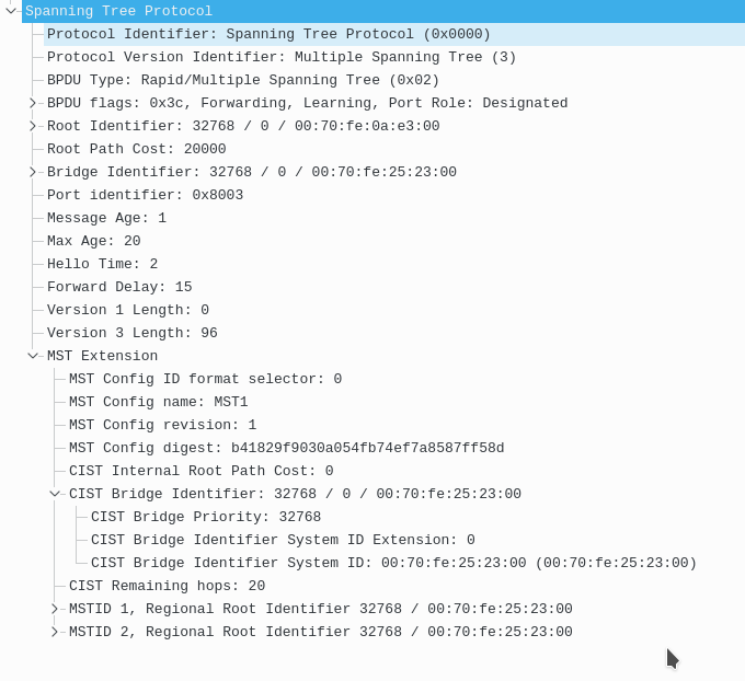

We have a bunch of new fields in the MST BPDU, and some changed.
First of all the protocol version identifier is what we would expect, 3 for Multiple Spanning Tree.
Here it says we have 2 version fields however I think that might be a decoder error.
We have the “MST Extension” which lists the following fields:
MST config ID format selector (reserved for future use)
MST config name:
MST config revision
MST config digest
CIST Internal Root Path Cost
CIST Bridge Identifier (with priority, extension id and mac)
CIST remaining hops
Finally we have MSTIs for every instance we have. In this case I have 3 instances, 0 (the CST), instance 1 for vlan 2, instance 2 for vlan 3.
Originally started as Cisco’s MISTP, then it was defined in a standard as 802.1S, now its under 802.1Q.
How does it work?
Decouples the vlan and STP instance.
Now we have a STP instance to vlan mapping that is user defined
Topology calculations are done by RSTP
Why would we do this?
We can scale much higher with the number of vlans we can support.
Takes redundant calculations away from control plane so that it wont have to compute 1000 similar instances of STP
MST has Regions:
In fact regions are the main enhancement that differs RSTP from MST.
A region is a group of switches that agree on 3 values:
instance name
revision number
vlan to instance mappings
There are different calculations based on intra vs inter region decisions:
Intra region –
All switches will know all details of that region
VLAN to STPIs are manually defined
undefined vlans fall into CIST (MST 0)
Inter region-
details between regions are unknown
different regions treat each other as giant switches
There are two root bridge elections in MST.
One root bridge election per region, for the regional root.
One root bridge election for the topology, for the CIST root.
Traffic between regions must first go to the regional root bridge, then must go through the CIST root.
A great illustration below, each MST region is seen as one switch.
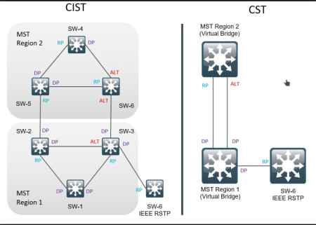

CIST = common internal spanning tree (where the BPDU exchange happens)
MST interoperability:
MST is backwards compatible with all versions of STP
Behaves like inter-region MST if using interoperability
CST root must be within MST domain
When migrating to MST, what should be changed first in the L2 network to NOT blackhole traffic?
The root bridge must be turned MST first or else it’s root ports will go into root inconsistent mode. Again this is because for MSt interoperability, the CSt root must be within the MST domain.
Command differences:
instead of doing ‘spanning-tree vlan x priority’ we now do ‘spanning-tree mst <instance> priority
Setting the MST root can be done via:
spanning-tree mst <instance> root <primary | secondary>
changing cost:
old : spanning-tree vlan x cost
new: spanning-tree mst <instance> cost
same thing with port id and bridge id changes
verification:
show spanning-tree mst
show spanning-tree mst configuration
show spanning-tree interface <int> detail
show spanning-tree mst <instance> detail
In MST our bridge priority still needs to be unique to guarantee a unique bridge ID, however we don’t use the VLAN ID anymore. Instead we add the MST instance number to the priority.
If you do not configure a vlan into an instance, it will be put into instance 0 by default.
Boundaries:
As we learned earlier from the BPDU most of the MST config is sent out via the BPDU except for the vlan to instance mapping. Instead a md5 hash of this configuration is sent out with the BPDU. If any of the region configuration items like name, revision or the md5 hash differ, the port is treated as a boundary port.
A port could be a boundary due to inconsistent configs between switches, or due to running different versions of STP.
A boundary port only sends IST BPDUs, never any BPDUs with Mrecords.
MSTIs mimic the port role of the IST at boundary ports.
PVST SIMULATION:
MST can also deal with PVST+ and RPVST. MST can detect PVST if it receives more than one BPDU on a port from multiple vlans. If it does it knows the neighbor is running PVST and thus it replicates the IST BPDU out on all vlans for the neighbor.
There are 2 rules for PVST simulation to work.
1 – If an MST switch is root, it must be root for all VLANs.
2 – if the PVST+ switch is root, it must be root for all VLANs.
The reason for both of these rules is because a boundary port can only be in 1 state, the state of the IST. Even when running PVST the BPDUs are actually just clones of the IST BPDU. This goes back to the idea that the MST region acts as one switch, and ones run CST towards the outside world, the IST.
What happens if these 2 rules are not followed?
The boundary ports are put into root inconsistent mode.
To facilitate compatibility with other versions of STP, MST utilizes the Internal Spanning Tree (IST). The IST, which is instance 0, is responsible for communicating with other versions of spanning-tree, or the common spanning tree (CST). The IST runs RSTP just like the MSTIs.
MSTIs:
MSTIs are the RSTP instances that operate within the region. Instead of sending a separate BPDU per MSTI, MST sends one BPDU with multiple entries inside. This is shown in the top page screenshot of the BPDU. The entries for each MSTI in the MST bpdu are called Mrecords. These are identical to the bridge identifier in terms of their contents.
What common misconfiguration can happen with MST that black holes traffic? Describe how it happens.
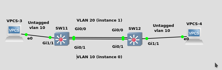

The common misconfiguration that can happen is manually pruning vlans from a trunk, or load balancing vlans with the IST. The issue with the IST is that it can block these links because it will treat them as loops. The solution for this is to NOT map any vlans to the IST, leave that for BPDU communication. Another solution is to make sure not to manually prune links from trunks so that a blocked link will not blackhole traffic.
In the example above the IST BPDU goes out on both ports g0/0 and g0/1 even though both are access ports for different vlans. This is because the IST is the only instance that sends BPDUs. Since vlan 20 is mapped to instance 1, an mrecord is added to the IST BPDU ONLY for port g0/0. However the common denominator here is that the IST BPDU goes out on both ports, thus it looks like a loop to STP and one of them will be blocked. In the above scenario vlan 10 was blocked and our hosts could not communicate!
As stated earlier the best solution is to map these valns to different instances, matching the topology, but always avoid instance 0. Leave instance 0 for the BPDU exchange. The less elegant solution is to not prune trunks manually, and to not have access trunks for load balancing.
f you need load balancing or more bandwidth, use etherchannels or L3 ECMP.
Main resource:
https://www.cisco.com/c/en/us/support/docs/lan-switching/spanning-tree-protocol/24248-147.html
http://blog.ine.com/2010/02/22/understanding-mstp/
Inter-region communication:
There is a CST root election (all regions can only have 1 CST root).
Then there is a region root election (the local region can have 1 root).
For traffic to go inter-region, it must first traverse the regional root bridge, then the CST root, then reach the other region.
Remember it as each region is treated as a giant switch.